Providers of laser
components and laser
related accessories
Near IR Display Plates & Probes
; return false;" class="fancybox)
IR Display Plates and IR Beam Probes are versatile instruments that present clear, high contrast images of all near IR laser beams. These displays are made with infrared sensitive phosphors which offer a variety of unique features, variable image retention times for pulsed lasers, high resolution for CW YAG, and a good response to Gallium Arsenide light-emitting diodes. All near IR lasers are capable of being displayed over a wide sensitivity range.
Our Model MAC24 IR Display Plate makes use of three different types of IR-sensitive surfaces to cover the varied near IR laser display requirements. Our Model MAC24 Series Beam Probes can be purchased with only 1 surface to fit your specific needs. The Beam Probes can handle less laser power, but they are more compact and can be fit into areas where the display plate may not fit.
- CW YAG, Pulsed ND, GaAs
- 200 watts continuous with display plate
- 0.5-1.6 Micron Response Range
Surface #1 is primarily designed for use with YAG Lasers. When illuminated by an ultraviolet lamp, this surface fluoresces a bright green. Striking the fluorescing surface with near IR light induces a transition which results in a quenching of the fluorescence. Therefore, the IR beam is displayed as a dark image on a bright fluorescent background. The sensitivity of this surface can be varied over a wide range by changing the intensity of the UV illumination; i.e, the distance of the UV lamp from the surface. The response time also depends on the UV illumination but is typically less than 10 milliseconds. This fast a response time is well suited for viewing rapidly changing YAG mode patterns; however, such a recovery time is too rapid to view a single pulsed laser.
Surface #2 is designed to be used with pulsed neodymium and other pulsed IR lasers. This surface fluoresces a bright green. Like surface #1, IR quenching produces a dark image display on a bright background. However, this surface has a much longer decay time which is ideally suited for viewing pulsed lasers. Depending on the illumination conditions, the image retention time can be varied from one tenth of a second to several minutes. The more intense the UV illumination, the shorter the persistence. When no UV illumination is used, and when the background illumination is dimmed, the phosphorescence of the surface will retain the laser beam pattern for several minutes.
Surface #3 is used primarily for viewing gallium arsenide light-emitting diodes and for probing CW YAG laser beams. This surface operates on a different principle than previously described. Energy is stored in the phosphor surface when it is exposed to fluorescent room lights or UV light. Near IR radiation stimulates the release of this energy as yell-orange light. Consequently, the beam appears as a bright image on a dark background. After the phosphors have absorbed a given amount of IR energy, the surface can become depleted. The beam must then be moved to a new area of the surface or the surfaced recharged.
All plate and imaging surfaces have a matte finish for safe beam displays, but we recommend using safety eyewear for all laser related applications.
Near IR Display Statistics
DISPLAY CHARACTERISTICS
| surface 1 | surface 2 | surface3 | ||
|---|---|---|---|---|
| CW YAG & High Rep. Rate Nd | Saturated Display (1) W/cm2 |
1000-8 | -- | -- |
| High Resolution Display (2) W/cm2 |
8-0.1 | -- | -- | |
| Minimum Power Density (4) W/cm2 |
0.1 | -- | .0003 | |
| Depletion Energy Density (3) J/cm2 |
-- | -- | 2 | |
| Pulsed Nd | Saturated Display (1) J/cm2 |
-- | 7-3 | 7-3 |
| High Resolution Display (2) J/cm2 |
-- | 3-.3 | 3-.3 | |
| GaAs Diode-- .9u | High Resolution Display (2) mW/cm2 |
-- | -- | 50-.1 |
| Minimum Power Density (4) mW/cm2 |
-- | -- | .02 | |
| Minimum Focused Power mW |
-- | -- | < .001 | |
| Depletion Energy Density (3)mJ/cm2 |
-- | -- | 80 |
SPECTRAL CHARACTERISTICS
| surface 1 | surface2 | surface3 | |
|---|---|---|---|
| Stimulation Wavelengths micrometers |
.7-1.6 | .48-1.6 | .53-1.6 |
| Emission Wavelengths micrometers |
.5-.6 | .48-.57 | .54-.62 |
| Excitation Wavelengths micrometers |
< .43 | < .48 | < .53 |
| Resolution lines/in. |
> 300 | > 50 | > 50 |
| Image Decay Time seconds |
.005 | .1-200 | .005-.05 |
DAMAGE LIMITS
| display plate | beam probe | |
|---|---|---|
| CW Damage Threshold W/cm2 |
2000 | 2000 |
| Pulsed Damage Threshold (5) J/cm2 |
7 | 7 |
| Maximum Average Power W |
200 | 40 |
| Maximum Intermittent Power W |
1000 | 100 |

Near IR Display Plate (Surfaces 1, 2, 3)
Regular price: $281.00
Near IR Kit (includes IR Plate, Beam Probes, 120V Lamp & Case)
Regular price: $561.00
Ultraviolet Lamp, 110 volt
Regular price: $170.00
Ultraviolet Lamp, 220 volt
Regular price: $170.00
Near IR Kit (includes IR Plate, Beam Probes, 220V Lamp & Case)
Regular price: $592.00
Near IR Kit (includes IR Plate, Beam Probes, 220V CE Lamp & Case)
Regular price: $634.00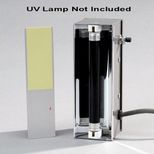
Near IR Beam Probe MAC24-1 (Surface #1)
Regular price: $94.00
Near IR Beam Probe MAC24-2 (Surface #2)
Regular price: $94.00
Near IR Beam Probe MAC24-3 (Surface #3)
Regular price: $94.00
UV Replacement Bulb for UV Lamps
Regular price: $43.00
Near IR Sensor Card, Reflective
Regular price: $149.00
Near IR Sensor Card, Transmissive
Regular price: $149.00